
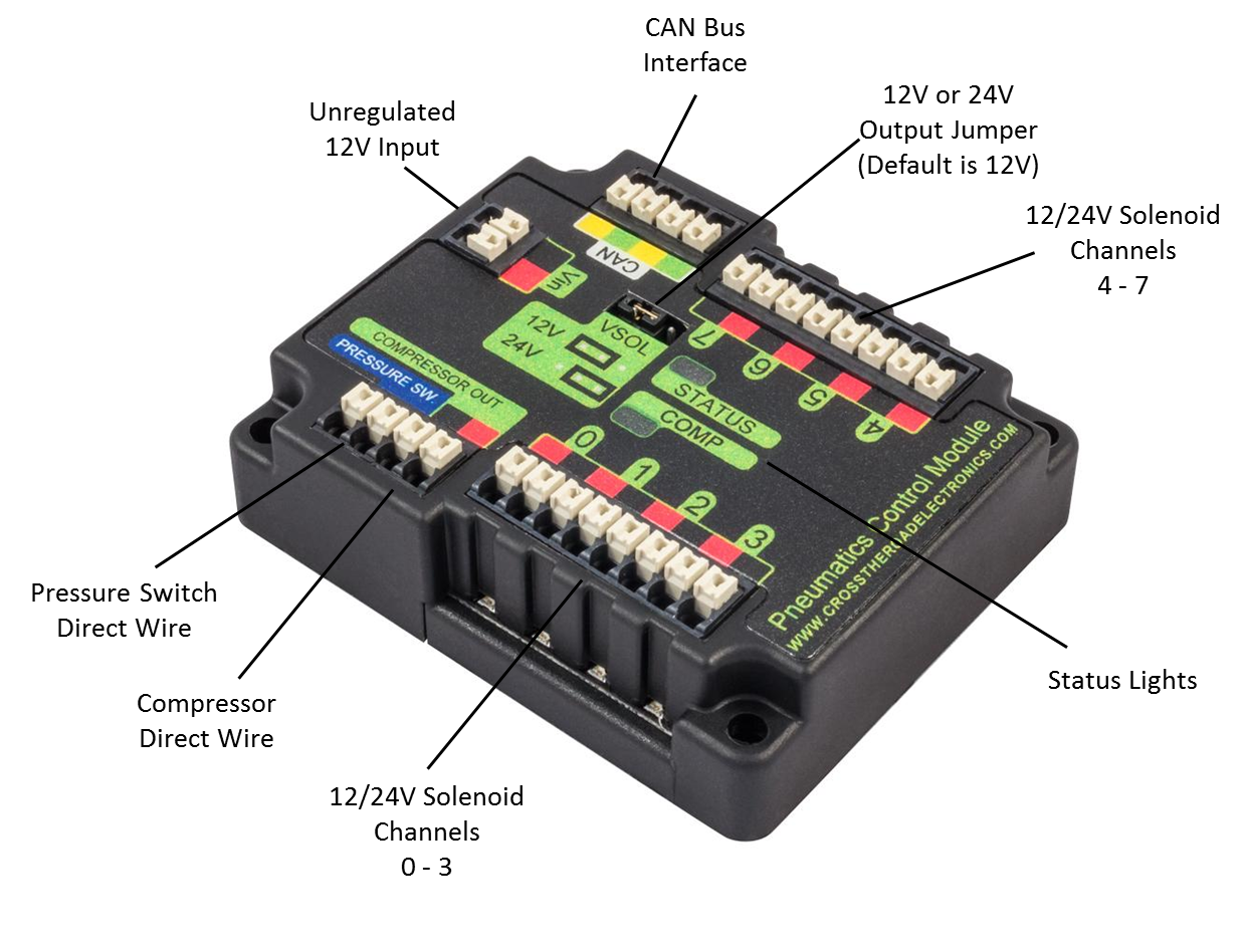
##Specs: 12 unregulated input power 8 solenoid channels Either 12V or 24V output (jumper selectable) CAN bus controllers Built-in direct control of Compressor and digital pressure switch
##Can I drive 24V solenoids and 12V solenoid using a single PCM? Not exactly; Each PCM supplies either 12V or 24V. There is a jumper setting in the center of the PCM which controls what the voltage all output channels will have. There is a jumper setting for both 12 and 24V. What ever the setting is, is global for all channels on the PCM. If the terminal is completely removed, the default voltage is 24V. But you should always have a jumper in place so that is it clear what mode the PCM is in. If you require many 12V and 24V solenoids use 2 PCMs with jumpers set respectively. See the other question below on how to provide power to more than 1 PCM. Depending on 2015 rules, you may also use the answer to the next question to run 12 and 24V solenoids off of a single PCM.
##Driving non 12V/24V solenoids possible? If you want to drive say a 5V solenoid, it is possible, but refer to the official rules for legality. The PCM switches the low (black) side not the high (red) side of each channel, so in theory if you wanted to power 5V solenoids for instance, you could make all of your 5v common, provide power to it externally, and connect only the ground to the PCM channels. This will allow you to switch the channels using the PCM even though you are not using the 12V or 24V supply from the PCM channels themselves.
##Can I use the PCM without CAN? No, CAN is the only way the PCM can connect to the roboRIO. However, to the end user this just means hooking up 2 wires, and calling the appropriate Labview or WPI PCM libraries. It is not much harder than that. Because the PCM is over can, the user can get feedback from the PCM and check real-time the state of each solenoid. Both battery voltage and solenoid voltage are available in the diagnostic webpage of the roboRIO, and available to the robot code in WPILib and LabView.
##How do I wire the compressor? The compressor and digital pressure switch are directly wired to a single PCM. The PCM has a built in controller which will automatically start and stop the compressor depending on the readings of the pressure switch. This frees up a relay and DIO port on the roboRIO when compared to the cRIO system. The user can take manual control of the compressor start/stop routine if they so desire using the libraries provided. You do not wire the compressor to a spike relay. See official rules for correct compressor wiring.

##Being that the PCM and the VRM share a common 20A fuse on the PDP and at the moment and teams are using the VRM to power the D-Link for Robot comms. Is there ever a possibility that the compressor starting and stopping, or a shorted solenoid channel can blow the 20A fuse on the PDP, and thus bring down the D-Link as well?
No this is not a concern. The PCM monitors for both short circuits and absolute current consumption of the compressor output. The solenoid channels are also monitored for shorts as well. Remember the PCM is a computer the Spike is just a relay. The reaction time is in microseconds, much faster than the fuse time of the 20A fuse at 30A (apx stall current of the Thomas comp)
We have replaced the fuse on our Beta PDP with a 15A fuse to put extra stress on the system, and have not blown it yet under normal use.
However, with that said, anything is possible, and teams have found ways to blow the 20A ATX fuse by stalling the compressor motor for long periods of time, shorting out the VRM wires, etc. So if the rules allow, I will ensure my teams powers the D-link from a separate VRM (or other legal buck-boost regulator that is connected to one of the unregulated 30A channels on the PDP. This will ensure that at no point will the compressor and D-link be on the same fuse. I recommend other teams do the same. The D-link is the life-blood of the Robot.
##My PCM is blinking Red what do i do?
Well this signals a fault. All of the faults are specified here: XXXXXXXXXX
I would first check your wiring and make sure you have green to green pins connected everywhere, and yellow to yellow pins connected everywhere. Then make sure the PDP board is the last item in the bus physically, and the roboRIO is the first item in the bus physically based on wiring and that the terminal resistor is set to “on” on the PDP board Finally ensure the roboRIO, PDP, PCM and any other CAN devices all have adequate power Lastly, ensure the roboRIO, and All CAN devices are flashed with the latest approved firmware, and the roboRio has code deployed.
Make sure you don’t have any shorts on the PCM solenoid channels, or compressor channel
You can use the roboRIO webpage to see all CAN devices and any faults on the device. You will need to correct the fault before the red light goes away.
<img src=”../../Images/pcmfaults.png”<
##For teams wishing to add more PCM modules or VRM modules, is there any recommendation on how they can power the additional modules?
This is a question for FIRST, and the official 2015 rules. Beta teams have been connecting additional VRM’s and PCM’s directly to 1 of the 16 motor channels and allow more than one to be connected to any given channel. They both take in unregulated 12V.
We have also connected 2 devices on a single 30A channel without problems, however defer to FIRST and the official 2015 rules for correct wiring.
##Does the PCM have any other features over CAN? Yes, the PCM logs all faults. Compressor faults are both momentary and sticky meaning you will see a red status LED while the fault is occuring and an orange LED that is persistant across power cycle (sticky fault) indicating that a fault has occured. The exact type of fault is revealed in the web interface of the roboRIO.
##Do I need to wire the CAN bus on the PCM?
Yes, the PCM can not receive or transmit signals from the roboRIO without its CAN terminals having been properly wired. When wired correctly, the CAN status light will be green.