
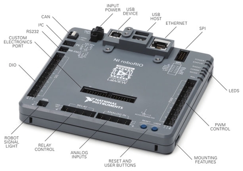
Specs:
Dual-Core Arm Cortex A9 @ 667 MHz 256MB RAM for System Memory 512MB NAND for NonVolitile Memory Runs Linux Kernel patched with pre_emtRT Input Power: 6.8 to 16V (brownout from 4.5 to 6.8VDC)
PWM: 20 (10 dedicated on PWM Rail, 10 shared on MXP) DIO: 26 (10 dedicated on DIO Rail, 16 shared on MXP) Relay: 4 Dual-output channels (FWD/REV) Analog: 8 Analog Inputs, 0v-5V, 12-bit 500 thousand samples per second Analog: 2 Analog Outputs, 0v-5V, 12-bit 340 thousand samples per second Serial: i2c, RS-232, TTL, SPI USB 2.0
What If I accidently plug into 24V power?
The new roboRIO will not be damaged. It will sense any voltage over 16V and safely shut down the systems which can not handle the voltage. You will need to remove the 24VDC supply and provide a suitable input voltage before the roboRIO can start up again.
Can I program over USB, Ethernet, and WIFI?
For all languages, deploying code using previous cRIO methods still work. That is, programming via Ethernet tether or wireless using a (D-link in AP mode) are all supported.
The roboRIO offers the added ability to program over the USB device port. The USB drivers for the roboRIO emulate an Ethernet controller when plugged in via USB. When connected via USB the Rio can be located at the IP address 172.22.11.2. Since the Rio also uses mDNS, you can use your driverstation via USB, Ethernet, or WIFI without changing any Ethernet settings as you switch between interfaces. If you would like to learn more about mDNS and how it is used on FRC please check out the FMS FAQ.
The USB drivers are installed on the computer when the FRC Utilities are installed which is provided in the official software released by NI.
How do I set my team number and IP?
You no longer need to set the IP address for the roboRIO. The new 2015 system uses mDNS and dynamic addressing to find all devices. Static IP addresses are no longer needed. To learn more about mDNS as it applies to FRC see the FMS FAQ
Your team number will be assigned to the roboRIO when you image the Rio for the first time. After which you can access the roboRIO using roborio-2168.local (replacing 2168 with your own team number, DO NOT prefix 0 for 3 digit teams).
So, if your team 359 for example, after imaging your roboRIO you can access it via Ethernet, Wifi, or USB using the single address roborio-359.local, which will resolve to the IP address of the roboRIO using mDNS. (Using roborio-0359.local will result in error).
For those teams wishing to assign their own static IP to the roboRIO you can still do this through the web interface. Once the roboRIO has been successfully imaged, navigate to http://roborio-2168.local, and check your network settings. You can login as admin and change the Ethernet port from dhcp to static and assign your own 10.TE.AM.2 address. The mDNS address will still work correctly even when the Ethernet port is set to static.
On Team 2168, we still manually set all network devices on our robot (including the roboRIO) to a static IP.
You can always check all of your network interface settings, and modify them through the web interface of the Rio. You must be logged in as admin to make any changes.
How do I access the roboRIO webserver?
Simply navigate to any of the roboRIO’s IP address from any computer on the same network. i.e http://roborio-2168.local (replace 2168 with your team number) will work on any interface using mDNS, http://10.TE.AM.2 if you assigned a static IP or http://172.22.11.2 when using the USB cable.
If this is your first time starting up the roboRIO, the Ethernet port is set to DHCP, and the USB port is configured to IP 172.22.11.2 address when connected to a computer that has the USB driver installed (supplied when FRC Utilities are installed).
Once you determine the IP address of the roboRIO, make sure your network interface card is also on the same subnet as the roboRIO, and you can navigate to the roboRIO in any browser which supports the Microsoft silverlight plugin to view the roboRIO webpage.
Note: Fellow linux users, silverlight doesn’t mesh well with *nix system. If you are on a linux machine you can try to install moonlight (which is a port of silverlight, unfortunately NI has no alternatives to access the WEB site other than through the silverlight plug-in at this time)
Click the login button in the top right corner and login with the admin user.
How do I access the Linux Operating System on the roboRIO?
The roboRIO is a headless device, meaning it is designed to run without using a display. If you would like to access the underlying linux filesystem you will need to use another device to do so. You can access the linux operating system in any of 3 ways:
- Use a shell terminal through SSH
- Use SFTP through a client like filezilla
- Use FTP through a client like filezilla
The method you choose is largely based on what operation you are trying to berform.
Using another computer you can use the secure shell protocol to access the roboRIO. You will need to connect to the roboRIO via Ethernet tether, WIFI, or USB and either know the IP address of the roboRIO, use mDNS to resolve the address, or use RS-232 with console out enabled (for shell terminal only).
Shell Terminal
From Linux or Mac: Open ‘Terminal’ and type ssh -l admin <IP of roboRIO>
From Windows install putty and configure it to SSH to the roboRIO IP address.
When asked for a password leave it blank and hit enter
Using SSH, you will have terminal access to the roboRIO filesystem and can run linux based commands, create/delete files or folders etc and execute and stop programs and services on the roboRIO.
SFTP
- Add a SFTP client to your web browswer. Filezilla client is freeware
- Configure it to connect to the IP address of the roboRIO
- Login using the ‘admin’ user
- You will see a folder structure of the roboRIO which will allow you to navigate its file system
You can use this method to browse the file system on the RIO, transfer files to/from roboRIO, read files, create/delete files or folders
FTP
It is possible to use the FTP protocol on the RIO, however only anonymous login is supported by default. The problem with that is when transfering or creating files via FTP, the file permissions are not set properly, so it is recommended that you use SSH or SFTP and avoid using FTP on the RIO.
What user name should I use to have ‘root’ access to the file system?
The Login information for the roboRIO from the factory is:
username: admin
password: <leave blank> (there is no password)
You can use this login via SSH or on the roboRIO webserver page to make configuration changes.
Why are the IO pins spaced so far apart, I like the way it was on the old DSC?
Well, in all honesty I don’t know. I would speculate it is to make it a lot easier for teams (rookies in particular) to plug/un-plug 3-pin header connectors. With the old DSC you could plug in a connector in pin 10, but acutally think you were plugged in pin 9 because of how close the pins were, and causing a debugging mess. The space avoids this debackle.
The pins are spaced by 2 0.1” headers. A 4 pin header can be used to bridge the gap, if a team desires to use two signal pins on 1 connector (for a quadrature encoder for example)
What do the LEDs on the RIO mean?
- Power
- Green = RIO input voltage is acceptable
- Orange = RIO input voltage is unacceptable
- Off = RIO is not powered or voltage is less than 4V
- Mode
- Solid Green = Robot in Teleop Mode
- Solid Yellow = Robot in Auto Mode
- Solid Red = Robot in Test Mode
- Off = Robot in Disabled Mode
- Status
- 2 Blinks Repeatedly = Error Detected in Software, roboRIO is put into Safe Mode Automatically, Re-image roboRIO using Imaging Tool
- 3 Blinks Repeatedly = User Directed roboRIO to start in “Safe Mode”, Recycle Power to exit “Safe Mode” and boot normally
- 4 Blinks Repeatedly = Software Crashed Multiple times, Most likely running out of Memory during program run
- Continuous Blinking = Catastrophic Unrecoverable Error, FileSystem is corrupt, use Seial to Debug and Contact NI
- Off - roboRIO booted up correctly, no errors
-
COMM = Green means robot code. Red means comms with DS, but no robot code.
-
RSL = Solid means powered, but disabled. Blinking means enabled.
- Radio = Inactive for FRC
How do I upgrade the image or install new firmware?
So far, for Beta testing, the roboRIO software has been delivered in two parts, a firmware, and an image. The firmware provides the bootloader, “Safe Mode”, and firmware for the roboRIO. The image is to load the FPGA, operating system, linux file system and default settings.
The user can upgrade the firmware over Ethernet tether, WiFi or USB. USB method is preferred and you should use that when ever possible, although we have had no problems updating the system over Ethernet/Wifi.
The image and firmware will be provided via an FRC Tools Software installation by FIRST/NI which can only be installed on a Windows 7/8 computer running 32 or 64 bits. While it is possible to flash the firmware from another Non-Windows computer using the website, the roboRIO Image Tool is a Windows only software and so Windows must be used to image the roboRIO at the very minimum.
Please see official instructions for firmware and imaging here:
ScreenSteps Flash roboRIO ScreenSteps Image roboRIO
Firmware Upgrade:
- Connect to the roboRIO via USB and ‘power-on’ the roboRIO.
- Login to the roboRIO webpage using your internet browser (You will need to have silverlight plugin). (Labview teams can use webpage or NI Max, Java/C++ teams must use Webpage).
- Navigate to http://roborio-TEAM.local (where TEAM represents your team number) or use http://172.22.11.2 when using USB. Login using “admin” as the user name and leave the password field empty. Click on the roboRIO icon and select upgrade firmware.
- Browse to the firmware you wish to use and apply (Typically in C:\Program Files(x86)\National Instruments\shared\firmware\FXXX\).
- The roboRIO will update the firmware, and if successful the new firmware version will be shown on the webpage. If not, just try again.
Image Upgrade:
- Connect to the roboRIO via USB and power-on the roboRIO
- Open the roboRIO Imagine Tool installed when the NI tools were installed (Typically in C:/Program Files(x86)\National Instruments\Labview 2014\projects\RoboRio Imaging Tool\).
- Then, select scan to find the connected roboRIO.
- Enter your team number, select format controller, and select the image you wish to use. Then click on “Format”.
- Formatting will take a few minutes, and once complete the program will notify you.
- The new image version will show on the Image Tool.
- Verify the roboRIO Power is Green and Status light is off (that means all went well).
- Java Teams Only (Reload the Java 8 Virtual Machine (JVM) on roboRIO see Java FAQ.
- All Teams - Upload Code to the roboRIO.
I did something to the roboRIO, and now I can not communicate with it at All. HELP? Is it Bricked?
No. Its nearly impossible to brick this thing. Follow these steps to regain communication.
When we tried to image the roboRIO prior to installing a compatible firmware we noticed this caused a state where we lost complete communication with the Rio. Upon start up, the power light was green and the status led was solid for the first 3 seconds and then flashed about 2 times a second for the remainder of the time. Power cycling or hitting the reset button alone during this time, did not change the outcome. The Rio would start up and the status led would start to blink at this constant rate.
During this time, all power to the peripherals seems to have been off. The USB port and Ethernet ports didn’t seem to be powered anymore so the Imaging Tool could not find the device and the Ethernet link was down. We were unable to establish any link or comms to the roboRIO.
If you experience the above symptoms, hold down the reset button for 5 seconds and after release the roboRIO should start back up. This puts the roboRIO in “Safe Mode” and loads a default/clean filesystem from the factory. The status LED should change. We noticed it started to pulse, about 3 blinks then pause, then 3 blinks and pause, and continue this way. Follow the below general debugging guideline to get the roboRIO back up and running.
- Use the status lights of the roboRIO to determine what could potentially be wrong. Ensure the power light is green and take note of what the status light indicator. If the power light is off, or orange, ensure the roboRIO is getting proper 12V DC input.
- If the status light is flashing use the answer to the previous question to determine what it means. If the status flashing 2 or 3 times a second and the power light is green, we can recover the roboRIO by flashing and reimaging.
- Hold down the “User Button” on the roboRIO for 5 seconds then release, this puts the roboRIO in “Safe Mode”.
- Attempt to Flash the roboRIO using the steps provided above, and then try to reimage the roboRIO using the imaging tool. Ensure that you are using the latest firmware and image versions provided by FIRST/NI.
After putting the RIO in “Safe Mode”, I notice all the peripheral ports were back up and we were able to http back into the RIO using the initial static IP setup. 10.TE.AM.2., the mDNS worked as well (http://roborio-2168.local) The status of the RIO was “Safe Mode”, no software, as shown by the webserver. If you did not have a static IP set, you can use the USB port to have Ethernet access to the roboRIO.
You can now login to the roboRIO webpage, and update the firmware and re-image the RIO, the RIO should now resume normal operations.
What is CAN?
CAN is a 2 wire serial bus mostly used in cars. Its an interface with a specific protocol just like I2C or RS-232. We can use it in robotics to communicate with multiple CAN devices such as the pneumatics control module, the power distribution board, and different motor controllers such as the Jaguar and CAN Talons. The CAN bus needs to be terminated by resistors at each end to prevent reflections. The roboRIO has a built in hardwired terminal resistor so it should always be placed at the beginning of the bus. The 2015 Power distribution panel has a jumper selectable terminal resistor, so you can place the PDP at the end of the bus, and have any number of CAN devices between the roboRIO and the PDP board. The CAN interface is a differential signal, so be sure to use a twisted pair wire to prevent against EMI. “Stripped CAT5 pairs work well ;)” - Lansing
How do I connect to the internet using the roboRIO
When the roboRIO ships from the factory, the default settings for the roboRIO Ethernet port is DHCP. So if you plug the roboRIO into a network switch that has internet access and a DHCP server (like a router), then the roboRIO will automatically connect to the internet.
If you choose to set a static IP on the roboRIO and assuming you are connected to a network that has an internet connection, you need to set the default gateway and DNS server on the roboRIO manually (in addition to the IP address). To do this, use your browser to connect to the roboRIO webserver and click on login using admin as the user name, and leave the password blank. Select the “Network interfaces” Icon, and under eth0 modify the default gateway and provide a DNS server. Here is a pic of what our setting look like:

As long as the default gateway leads to the internet and the DNS server is active you will have internet access on the roboRIO. You can test your internet connection by connecting to the roboRIO via ssh and running this command in the terminal
wget www.google.com
If you see a file downloaded, your RoboRio is connected to the internet, and DNS server is working properly.
Can I install 3rd party packages/software on the RoboRio?
Yes, the roboRio uses OPKG package manager. You can run OPKG from the terminal and install packages that way. There is a public repository for the RoboRio released by NI that already has many useful applications and comes loaded by deafult.
Simply run the following commands in the Rio terminal while the rio is connected to the internet to see what packages are available in the NI repo for installation:
opkg update
opkg list
use opkg install <package> to install your package.
The RoboRio is an ARM processor based on soft VFP registers with NEON instruction support. You can use any binary that has been compiled for ArmV7 with softFP on the RoboRio.
If the NI repo doesn’t have what you are looking for, luckily, you can make use of the Angstrom Repository to load additional software onto the RoboRio. The Angstrom Repository has over 5000 different packages which are compatible on the Rio. To add the Angstrom Repo to the RoboRio package manager, follow the steps below:
- SSH into the RoboRio using “Putty” on windows or “Terminal” on any Mac or other linux based computer.
- Login using
adminas the username and leave the password blank (just hit enter). - Use VI to create a new feed source for opkg
vi /etc/opkg/angstrom-base-feed.conf. - Hit the
ibutton on your keyboard to enter insert mode in vi. - Paste this line into the file
src/gz angstrom-base http://feeds.angstrom-distribution.org/feeds/next/ipk/eglibc/armv7a/base/. - Hit the
escbutton on your keyboard to exit insert mode in vi. - Type
:wqand hit enter to save the file and exit VI. - You should now be back at the terminal prompt $
- type
opkg update. - If connected to the internet, your RoboRio will now download the list of Angstrom packages you can safely install on your RoboRio.
- use
opkg install <package>to install new software on the RoboRio. - use
opkg updgrade <package>to upgrade packages. - use
opkg list-installedto see what you already have installed on the RoboRio. - use
opkg search <package>to see what you can install from the Angstrom repo onto the RoboRio.
Can I use 3.3V sensors on the RoboRio?
In short - yes. The power output pins on the RoboRio DIO pins and analog pins are all 5V outputs by default. There is a jumper to set the DIO pins to 3.3V output but is internal to the Rio and you must remove the case to do so. This is not something FIRST or NI envisons teams to do frequently. I would suggest that you stick with one voltage source for all sensors, or use external supplies instead of going into the RoboRio.
The jumper is located inside the RoboRio case next to the connector for DIO9. See attached photo for details. When no jumper is installed the voltage output is 0V.

The jumper only affects the DIO power pins on the built-in DIO connectors, it does not affect the analog power output, or any power output pins in the MXP port. The MXP has both power supply rails included, so you can use either 5V or 3.3V supplies from the MPX without changing the internal jumper.
All DIO signal pins are 3.3V drive and 5V tolerant, so if you power your 3.3V sensor from an external source, the signal will be interpreted correctly on the IO pin without any jumper change for either 3.3V or 5V signals.
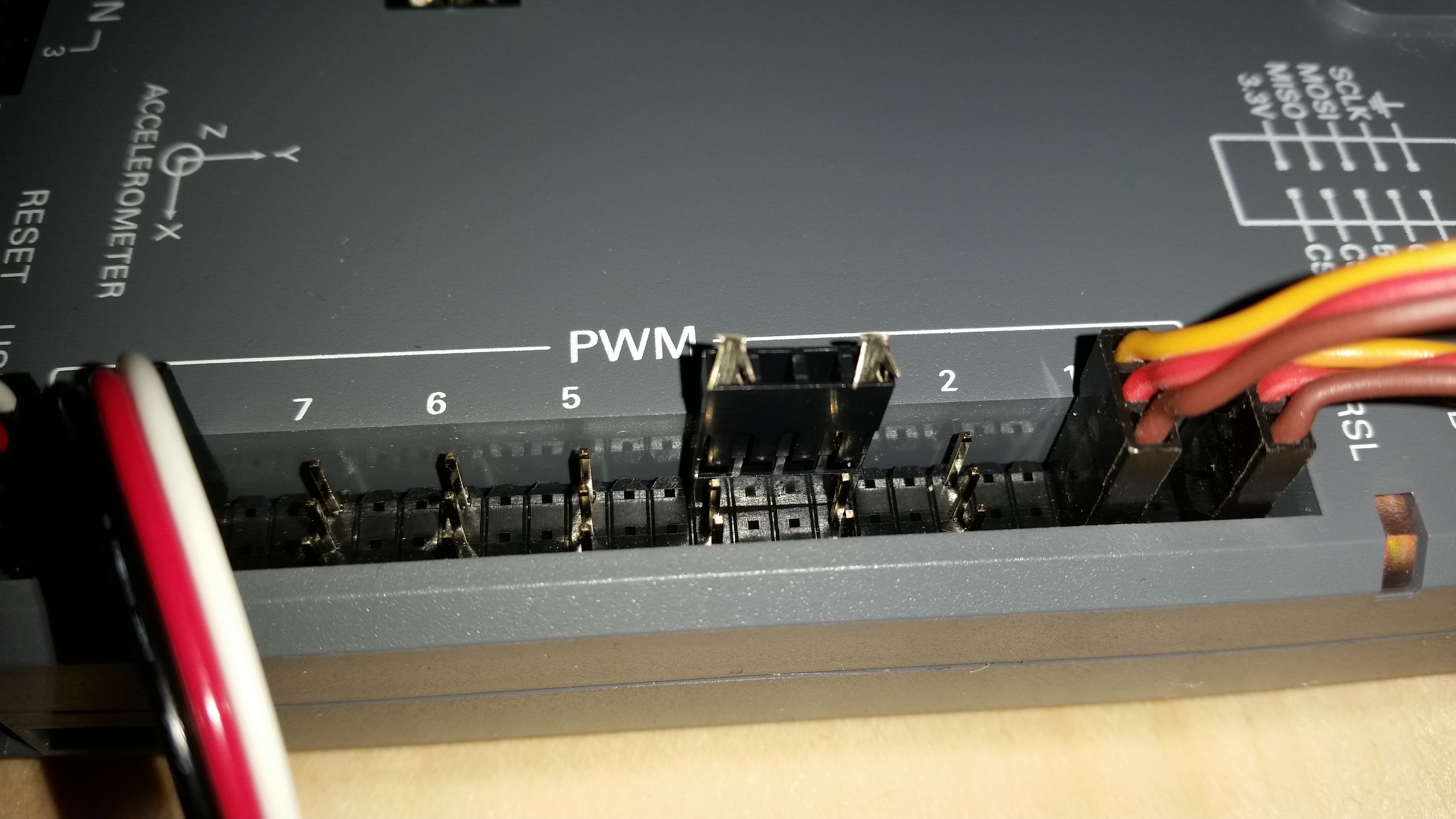
How do I drive 6V servos on the RoboRio?
Just plug it into any PWM port. All PWM outputs on the RoboRio are 6V output power (center pin), 5V signals (signal pin). There is no jumper cable to modify the output voltage (center pin or signal pin) of the PWM rail. All motor controllers for FRC have the center pin on the PWM disconnected (so they don’t use the 6V pin), they only use ground and signal. Therefore, the 6V output is always present, and used to drive a servo if a servo is connected to any PWM pin.
What happens when the RoboRio voltage drops?
As the input voltage drops below a specifed voltage, certain systems are turned off automatically. The brownout condition I believe starts when the input voltage to the RoboRio dips below 6.8V, at the moment it is unclear if it needs to stay below this level for any period of time.
The PDP power supply to the RoboRio is not regulated, the RoboRio regulates its own power internally. This was a concious decision made by the design team.
Here is the breakdown of the logic we noticed during brownout testing:
- input voltage is 7.5V and above
- All RoboRio Systems are fully functional, Power LED is Green
- input voltage Below 6.8V, Power LED is Organge
- RoboRio Power light goes from Green to Red
- All PWM Output signals are disabled (Motor controllers are neutral)
- 6V Servo Output power is disabled
- input voltage power Below 6.3V
- All DIO 5V output power is disabled (RoboRio and MXP)
- All 3.3V output is disabled (RoboRio and MXP)
- Digital Input and Analong input signal pins are still active
- input voltage Below 4.0V, Power LED is Off
- RoboRio Processor died
- No longer able to read any DIO channel states
- Driverstation Loss of Comms with robot
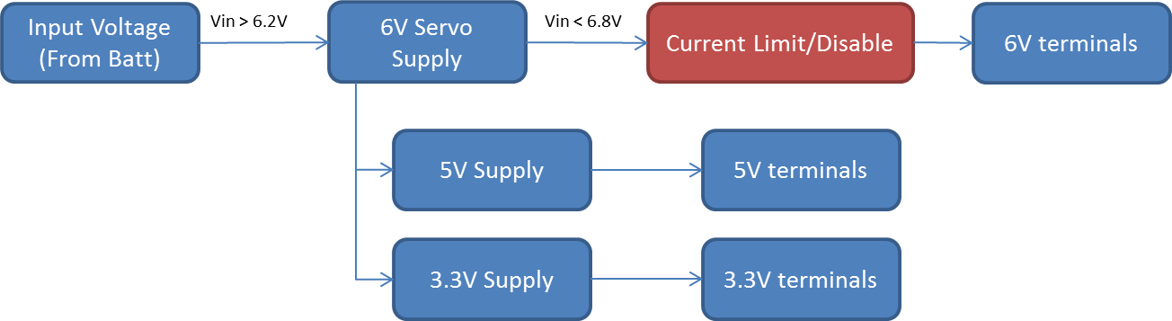
From my understanding, the regualtor topology on the RoboRio is such that the 6V supply feeds the 5V supply, and the 3.3V supply. So if the 6V source is lost, 5V and 3.3V power sources are lost as well. Currently, upon a brownout event, (VbattIn < 6.8V) PWM output and 6V servo power are deactivated, but the 6V supply is still operational (so 5V and 3.3V rails are still operational). When the RoboRio drops below 6.3V, the 6V regulator can no longer be sustained so the 6V, 5V and 3.3V power are lost.
This means there is now ~ 0.6V between when the motors are disabled and when the 5V and 3.3V supplies shut down instead of them happening at the same time.
I believe there is current work on a feature that will allow the FPGA to stop motor controllers in far less time. The plan is to actively send one PWM pulse of “idle” when commanded to disable by the watchdog / power monitor before stopping the generation of PWM signals. Because the motor controllers are not continuing to draw high current for as long, the voltage drop should be less severe. This should reduce the time from brown-out detection to load removal from 100 ms +/- 5ms to about 10 ms +/- 5 ms.
Here is a pic of the Regulator Topology:
Will we lose encoder counts while that happens (encoder brownout)?
This depends on how your robot is wired and what voltage level the electrical system is dipping too. If the robot is dipping below 6.3V and you are powering your encoders from the 5V source on the RoboRio, then yes, as the 5V supply dies, so will power to your encoder.
However, the RoboRio can read it’s inputs down to above 4V, so if you supply power to your encoder externally (using a boost regulator for example), then the encoder will still maintain its power, and the RoboRio will still be capable of reading the pin states until the input voltage is too low to run the RoboRio processor (below 4.0V).
The RoboRio monitors its input voltage level and coordinates brownout staging in order to prevent blackout of critical elements. This is the approach that is currently being tweaked.
The general approach of the brownout behavior is to disable high draw components – motor controllers – in order to stabilize the voltage level and avoid reboots and further faults. As mentioned earlier, the response is being tweaked in order to maintain the supply rails to sensors – both analog and digital.
One aspect of this, detailed by NI, is to identify which PWM devices are motors and which are servos. The FPGA will then be able to disable motors directly instead of simply removing their signal and waiting for their the controllers to timeout. This quicker response has not been tested by the alpha or beta teams, but it is a ~10X improvement in timing control of the circuit driver.
When a brownout does occur, the information will be accessible to robot code. Labview, C++, and Java libraries have been outfitted with new function calls that will return true or false depending on if a specific system is currently in the brownout state. Using these methods can help teams prevent control loop Integral windup. If the motor controllers outputs are zeroed by the FPGA, this can cause integral windup in control loops. If those control loops are aware that their set point was not what they requested, they can adjust their integral state. If the brownout is more severe and the supply lines to servos and sensors is interrupted, the robot code can know that absolute position of some mechanisms may need to be recalibrated.
If you are really worried about this situation, the best recommendation is to put your critical sensors, feeding control loops on a dedicated regulator, that will be sustained when the voltage drops. This way the sensor stays alive, and the RoboRio will be able to read the digital/analog signals as long as the RoboRio is still running.
The bus switch that adjusts the signals passed to the FPGA is powered by a supply that is sourced by the buck-boost that powers the controller as a whole. That supply operates down to 4.5 V. That means that if you decide to power your encoder with a supply other than the one provided and the provided supply browns out, the signals will still make their way to the FPGA. As noted earlier, if your sensor depends on pull-up resistors (like limit switches or banner sensors or open-collector output encoders) then you will also need to add pull resistors connected to your external supply. You should be able to test this by either using the new power API to disable the 5 V supply manually or by installing a jumper between 5 V and Ground which puts the supply in protection.
When the RoboRio browns-out, will I lose command of motor controllers?
Yes. When the RoboRio browns out, the power indicator on the RoboRio will turn orange, and immediately motor controller outputs will be disabled.
If you notice your robot is staggering/stuttering all of a sudden, it is most likely because your battery is on the edge of the RoboRio brownout point, and when the motors are driven the roborio disables outputs, which causes your voltage to raise above the Brown out threshold, enables the motors, which then browns the rio out again…and you enter this loop.
To be sure you are not browning out at a quick glance, when driving your robot, always ensure the power light on the RoboRio is solid green. If it is orange at any point, the roborio is browning out and you should check your power sources.
New power API have been provided for all languages so teams can detect the brownout condition in software. Please see the respective programming FAQ for more details.
Everytime I deploy code, immediately after the Driverstation says no “Robot Code”. What’s happening?
Well the “Robot Code” indicator in the DS means that your robot application is actually executing. If the code crashes for any reason, such as a null-pointer error, or other exception, the application will stop running, and the “Robot Code” indicator will go red.
This most likely means your code is crashing upon start-up, so check for runtime errors using netconsole or your general labview debugging methods.
When this happens, you will also notice the Comms light on the RoboRio go red. This means that Robot Code is not running.
How long does the RoboRio take to start up?
With the RoboRio off, and Driverstation application running on the DS computer, it took approximately 30 seconds from the time the RoboRio was switch on to the point when Comms and Robot Code was established.
##How long does it take to deploy code?
Well since we are a Java test team we can only comment for Java. Typically it takes about 8-10 seconds from the time we hit deploy in eclipse to the time the code is running and established Robot Code on the DS.
What are some of the linux based information I should know?
Kernel: 3.2.35 File System: UBI Boot Loader: uboot Init: SystemV
How do I put the RoboRio in “Safe Mode”?
Hold the Reset Button until the status light illuminates (about 5 seconds) and release, The RoboRio will rebot and the status light will blink 3 times repeatedly. This indicates the RoboRio is now in “Safe Mode”
To get out of “Safe Mode”, reboot the RoboRio by pressing the Reset Button, issuing a reboot Command in the terminal, or power cycle.
How to I commuicate with the RoboRio over Serial (RS-232)
The Serial Information is:
- 115,200 bits per second
- Eight data bits
- No parity
- One stop bit
- No flow control
You will need to buy a USB-to-serial adapter and make a DB-9 to 3-pin header cable. Follow Instructions here:
On Linux:
1. Install minicom sudo apt-get install minicom
2. Plug in the USB-to-serial converter and wait a couple of seconds
3. Find out which port the adapter is assigned dmesg | grep tty (output should be something like ttyUSB0)
4. Open second terminal window
5. Configure MiniCom with the above settings sudo minicom -s
6. Be sure to replace the port with the one found earlier i.e ttyUSB0
7. Exit Minicom, the modem should initialize, hit enter and the terminal should now show the RoboRio terminal (assuming the cable is correct)
On Windows: 1. You can use putty to establish a serial connection. Install Putty 2. Install drivers for your serial-to-USB converter. 3. Identify which com port your serial device is connected to using device manager 4. Open the putty application, In the main navigation sidebar, select connection->serial 5. Configure the paramters for the serial connection as identified above. 6. Click on session in the main navigation sidebar (com port at baud rate should be set) 7. Select the “serial” radio button 8. click open to start the serial connection
What is the MXP port?
The Modular Expansion Port (MXP) is an additional breakout that provides access to all the dedicated ports on the RoboRio and includes additional shared PWM pins/DIO pins/analog pins and serial interfaces. The MXP also has 5V and 3.3V sources. You can use this port to make your own custom board or buy pre-made boards.
Make your Own Board FIRST Compliance
Pre-made board from Rev Robotics
What does a shared PIN on the MXP mean?
A “shared” pin means that the pin can be used in a multitude of ways, and you can choose which way to use that pin in your robot program.
For example shared PWM pins on the MXP means you can either use that pin to provide a PWM signal (for a motor controller) or you can use it as a Digital Input Signal, or as a Digital Output Signal.
What is “Safe Mode”?
“Safe Mode” is a separate partition on the RoboRio that is installed when you load the Firmware. “Safe Mode” loads a clean default Linux File System in a RAM Disk. Any modification to the file system will be lost upon reboot. Safe-mode can be used to re-image the boot filesystem or to recover for other system crashes.
If there is no OS installed on the RoboRio, it will boot up in “Safe Mode” by default. This is the behavior you should expect to see when you first unbox your RoboRio from the factory. It will ship with a default firmware, but no image.
How do I run gui applications on RoboRio using X11?
To exable X11 forwarding:
- Make sure to add the angstrom repo to opkg (follow directions under 3rd party applications above)
- Install xauth
opkg install xauth - Modify the sshd config file
vi /etc/ssh/sshd_config - Hit
ion the keyboard to enter insert mode - Add the following 2 lines to the end of the file:
X11Forwarding yes
X11UseLocalhost yes
- Hit
escon the keyboard - Type
:wqand hit enter to save and exit - You should now be back at the prompt
- Type
export DISPLAY=localhost:10.0 - Restart the sshd server
/etc/init.d/sshd reload - Kill the connection by typing
exit - SSH into it again with X11 forwarding
ssh -Y admin@roborio-2168.local(on linux/mac) or by enabling X11 forawding on putty under connection->ssh->X11 -
If done correctly, there will be no X11 error once logged in You may see /usr/bin/xauth: file /home/admin/.Xauthority does not exist Thats a good thing, it means the rio created a ssh for your computer
- You can now run a gui application, and it will use x11 forwarding to show up on your development computer. Assuming you have X11 installed on your computer